
Custom ultrasound platforms
Engineered as one imaging system.
From transducer interface and low-noise acquisition through FPGA receive beamforming, GPU reconstruction, AI-assisted workflows, industrial design, verification, and production transfer.
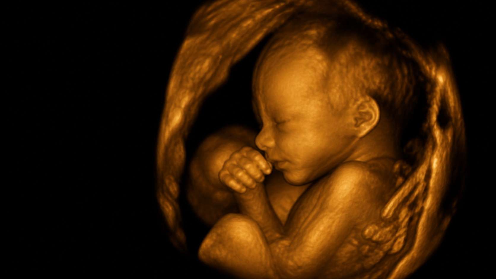
Concept 3D ultrasound visualization · Not for diagnostic use
01 Parallel-receive channel classes
02 Raw RF access on research configurations
03 Production boards or technology transfer
Handheld beamformer imaging output
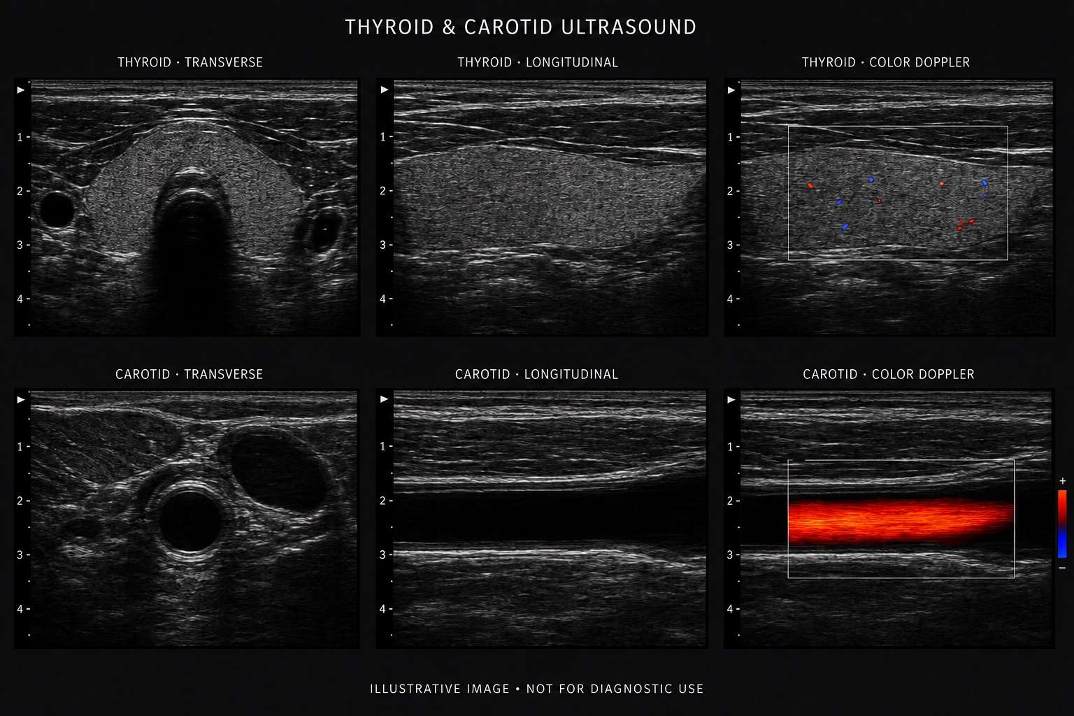
Image formation targets for point-of-care workflows.
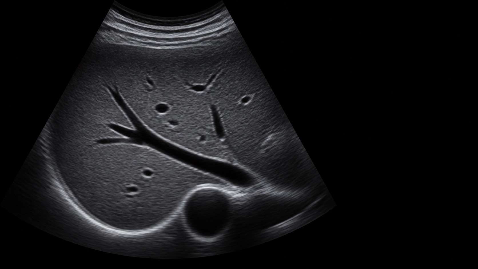
A representative visualization of thyroid and carotid workflows across B-mode and color Doppler, illustrating the imaging targets for ALEVA's handheld-class parallel-receive beamformer architecture with high-frequency linear arrays.
- B-mode
- Color Doppler
- Linear array
From channel data to a controllable image
Post-processing completes the imaging pipeline.
After receive beamforming and image formation, the post-processing layer prepares the frame for viewing. Display-oriented filters can then be tuned to the application and exposed as controlled user adjustments.
- 01Probe & AFEAcquired RF channels
- 02BeamformingFocused receive data
- 03Image formationB-mode / Doppler frame
- 04Post-processingDisplay-oriented filters
- 05Display & controlsUser-adjustable view
Interactive comparison
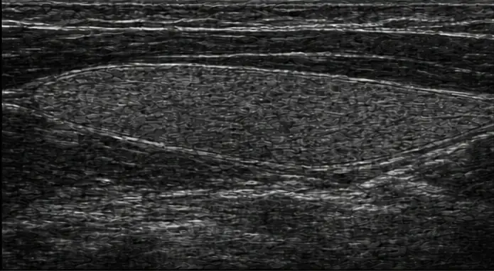
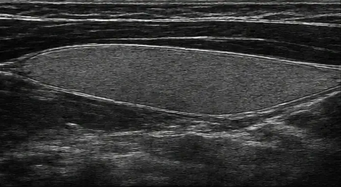
Inspect the post-processing stage.
Drag right to reveal more of the filtered appearance; drag left to restore the original.
 Filtered
Original
Filtered
Original
Autoplay starts by default. Drag, use the arrow keys, or choose a position to switch to manual control.
Illustrative comparison. Not actual filter output. Not for diagnostic use.


Technical depth, one accountable team
Four engineering layers. One product outcome.
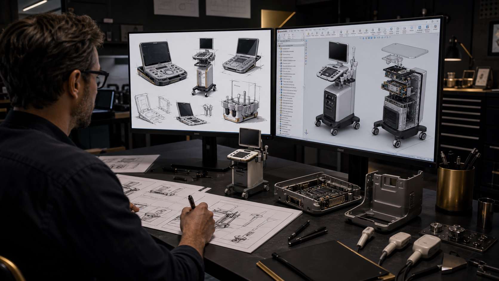
ALEVA can deliver one subsystem or own the connected path from acoustics to manufacturing. The interfaces are defined together so image quality, latency, power, thermal behavior, enclosure, and test strategy stay aligned.

GPU: reconstruction, plane-wave / synthetic-aperture processing, advanced modes, and AI-assisted imaging.

A controlled development path
Define. Architect. Prototype. Transfer.
Requirements and risks are made measurable before architecture freezes. Working prototypes then connect acoustics, electronics, firmware, imaging, mechanics, verification, and the intended production path.
See the engineering approach ↗- 01DefineApplication, probe, image, workflow, production.
- 02ArchitectInterfaces, partitioning, risks, verification.
- 03PrototypeHardware, firmware, imaging, enclosure, iteration.
- 04TransferRelease, documentation, production, support.
Technical program intake